
Understand and master the axial fan ventilation and fans design simulation with heliciel software:
The calculation and design of an axial fan for a blower or aeraulic ventilation system, is to dimension the diameter of the fan, the number of blades, the speed of rotation, the hub diameter and the twisting of the blades as a function of delta total pressure of the fan to be provided to compensate for pressure losses of the ventilation system ..
Try here to explain in four designs what goes into a fan that generates a pressure delta at a given flow
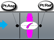
The total delta pressure of an axial fan (Dpt in pascals) is the difference between
the total pressure at the suction flange (PtAsp) and the total pressure at the discharge flange (PtRef).
This pressure difference corresponds to the axial thrust force P (Newtons) generated by the propeller divided by the surface of the S ring (m²) swept by the rotating blades:
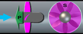
The thrust P is produced by the variation of quantity of movement(F=m*a)
between upstream and downstream of the blades. The fluid (considered incompressible)
is accelerated from V0 at upstream, to V2 downstream, via a speed V1
at the blades level.This acceleration energy intake (axial induced velocity)
is produced by the blade lift, rotated by the motor.
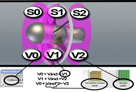
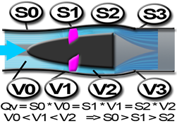
The flow (Q) being constant to minimize the turbulent losses, the hub will be sized and leads to better adjusting S0 S1 and S2 to the speed variations (continuity Equation) The enlargement S3 decreases the speed (V3 = V0) and transfer the dynamic pressure into static pressure (Bernoulli).
V0 = V3 implies that delta P total = DeltaP static(pascals) = PtRef-PtAsp = thrust (Newton) * Section S1(m²)
Heliciel includes a "Wizard ventilation". This tool greatly facilitates the design of axial fans axial flow according to specifications aeraulics type loads. Just enter the flow of the system and adjust pressure parameters to create the custom fan and edit operating curves (yield, total pressure delta), depending on the flow.
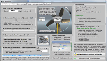
This "Wizard fans" has been specially designed at the request of ventilation consulting firms and ventilations designers, as a way to master independently the total design of their systems ventilations.
A study by design approach feasibility of velocity triangles, depending on the pressures and flow rates required, allows pre-size the blades, before creating the final 3D modeling.
The theoretical sketch automatically updated by heliciel, shows the angles of entry and exit of the fluid levels of diferent radii of the blade. These angles are determined by the velocity triangles to the inputs (points1) and outlet (points2) of the profiles:
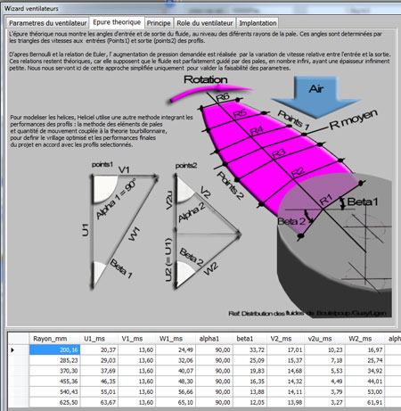
Euler and Bernoulli equations show that the increase from applied pressure, is performed by the variation from speed between the input and the output. These relationships are theoretical, because it assumes that the fluid is perfectly guided by the blades, infinite in number, having an infinitesimal thickness. Here we use this simplified approach only to validate the feasibility of the parameters. To model the propellers, Heliciel uses another method integrating performance of the profiles: the method of blade elements and amount from movement coupled to the vortex theory, to define the optimized twist and the final performance of the project in accordance with the selected profiles.
The ambition of this fan creation wizard axial propellers, is to improve the energy efficiency of ventilation systems and lower operating costs by providing technicians, draftsmen and designers an easy to master and corresponding to the standards of specifications encountered in aeraulics.
The role of the ventilation fan in a ventilation system:
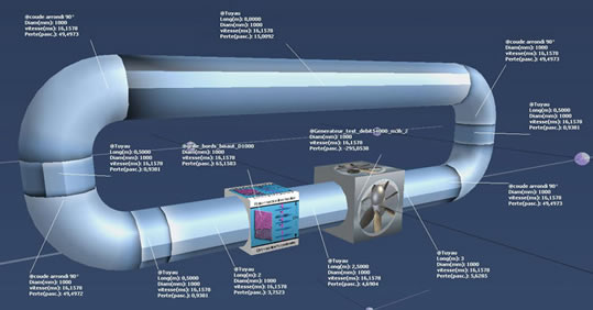
The fan generates the "Dpt" (Delta's total pressure, static + dynamic) equal to the total consumed by the flow pressure at the given flow. Here are 4 examples (images MECAFLUX Pro3D) at the same flow and same fan diameter::
- Open Systems: At desired flow, the fan must provide Dpt equal to the pressure losses singular + REGULAR + dynamic pressure output (if it is not already integrated in the singular losses):
Exemple 1: The system rejects the high-speed fluid dynamic pressure lost is important:
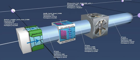
Exemple 2: The system rejects the low speed fluid lost dynamic pressure is low:
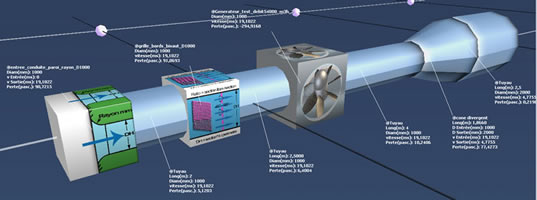
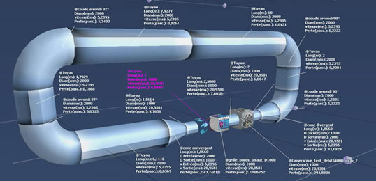
- Closed systems: At desired flow, the fan must supply a total pressure equal to the delta pressure losses singular + regular. (The dynamic pressure output is recovered at the input)
Exemple 3: Speed feedback loop (lower sections), the dynamic pressure lost is zero, but the pressure drops are important:
Exemple 4: Low speed loop back (large sections) dynamic pressure lost is zero and the pressure losses are low :
Some recommendations of implementations to avoid performance loss:
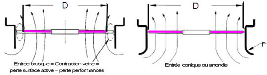
- sudden inlet=contraction losses
loss of active surface= performance loss - Tapered or rounded input = low pressure input
and use of the entire active surface
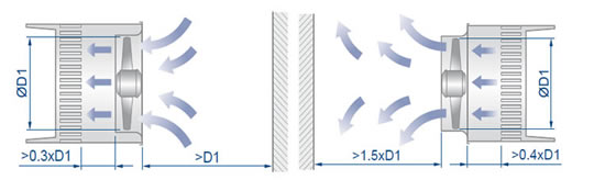
Distances between the rotor and the exchangers, distance of implantation, input or output
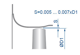
Space between the fairing and the tip of the propeller blade
 Global site map
 Mecaflux
 Tutorials Mecaflux Pro3D
 Tutorials Heliciel
 Mecaflux Store
 Quotes, Orders, Payment Methods
 project technical studies